GFS Power

How to Build a DC Power Supply That Works

September 6th, 2016 by Raymond Gibb

GFSPower_DC Power Supply Design_161115The purpose of a DC power supply is to take an AC current and convert it to DC. Simple! The main components of this are the input transformer, the rectifier, a ‘smoothing’ circuit and a regulator.

DC power supplies are used when it’s simply not practical to use batteries to power a circuit. This is the case in situations where a large computer server has been installed, or where telecommunication equipment needs a steady, high quality source of power. DC power supplies can come with built in, in-line backup batteries so that if the AC source fails, the batteries are immediately engaged. The following are the components integral to DC power supply design.


The input transformer

An input transformer has to do two things. It has to change the voltage of the incoming current (usually reducing it) and it has to isolate that incoming current from its own output circuit. The voltage that it produces needs to be as constant as possible, so a transformer where a constant voltage is maintained to within 1% variation under all line conditions is desirable. The transformer, ideally, should be internationalised.

The rectifier – key component of a DC power supply

A rectifier takes the alternating (back and forth) current from an AC supply and passes it through a series of diodes, or switches, that only allow the current to flow in one direction. It does this by not allowing half of the cycle of current produced by the AC generator to flow through it – it cuts out one half of the cycle. But a device called a full-wave bridge rectifier doesn’t just cut out half of the AC flow ‘wave’; it takes advantage of this ‘negative’ part of the cycle too by directing the current through four diodes which keep both halves of the current flowing in the same direction with a series of checks and balances.

Smoothing things out with capacitors

To keep the output voltage of the DC power supply steady, a capacitor is added to the circuit. This acts as a reservoir for the current so that if the voltage dips, it can top up the power output. The output could drop as low as 0 Volts if any component of the AC current makes it through the circuit (this being the point at which the current flow reverses direction). By introducing a capacitor, an average voltage level is maintained.

The regulator – a final refinement

The smoothing out process is further enhanced with a regulator.


This takes the DC current generated by the DC power supply then modulates its output voltage so that regardless of what it receives, or variations in the load it is driving, it delivers a consistent voltage.

This is important for electronic devices that rely on steady voltage.

Safety Principles of a DC Converter

August 21st, 2016 by Raymond Gibb

There are two types of electrical current – alternating and direct. Known as AC and DC, the two have different applications. The former is the power supplied to your home or business and is currently powering any air-conditioner, heater or fan you may be using. DC is the current in the computer you are using, since it is used for powering electronic devices such as smartphones, televisions and hi-fi amplifiers.

Because of this, sometimes AC needs to be converted to DC. But DC may also need to be converted to a different voltage. Here’s a look at current and voltage conversion practices – and how DC converters save lives.

Converting AC to DC  

Since the current supplied by the electrical grid is AC, all the devices that use DC must have a converter inside them. These AC DC converter circuits are usually small and built in to the device or a ‘wall wart’ (e.g. a laptop). When a large piece of DC equipment is used, a dedicated DC converter must be used. The core of any AC to DC converter is its rectifier, which takes alternating current and passes it through a diode, a device that only permits the flow of electricity in one direction. Alternating current takes its name from the fact that during generation the current flow constantly changes direction. To power electronic devices with microchips inside the current must flow only one way – hence ‘direct current’ – and this is what the diode achieves.

Voltage stabilisers for current regulation

There are also times when a DC source is unsteady and needs to be converted to a reliable constant voltage. This can be the case with batteries – the source of any mobile DC supply – which can output a varying amount of charge that subsequently interferes with the equipment it is powering. DC converters can be paired with voltage stabilisers which provide a continuous, regulated supply of power over the life of the battery. This doesn’t mean the battery will never lose its charge, but its gradually diminishing capacity over time will not affect voltage-sensitive equipment.

Stepping down the DC current: DC to DC converters

A DC to DC converter system changes the voltage of a DC current. This is necessary in car sound systems where the 12V battery source needs to be converted to a lower voltage to power a CD player or charge a smartphone. Conversely, step up converters turn the 1.5V of a battery to a stable 5V to power an MP3 player, or boost a car’s 12V to the 40V needed by its stereo amplifier.

Isolated DC converters: A question of safety

There are two types of DC converters, isolated and non-isolated. Non-isolated converters have no barrier between the incoming current and the outgoing.

This is fine when the ratio between the voltages is low or when the risk of the current escaping the device is not high. But imagine a piece of electronic hospital equipment that has leads connected to a patient that carry monitoring signals. The DC converter that supplies the extremely low voltage to the leads needs to be isolated from the original current for critical safety reasons.

If the voltage contained in a device is allowed to escape from a DC converter, the results can be electrical failure and damage to the equipment or even a risk to life. For example, if  the low voltage in a USB interface was not isolated from the 240V available at the power source, the results of a malfunction would be catastrophic for you the next time you went to use the USB device.

DC converters are a vital component not only in voltage conversion but in the safety of any DC electrical circuit.

How to Improve Power Supply Reliability 

July 21st, 2016 by Raymond Gibb

Power supplies are the unsung elements of electronic devices. Not as exciting as a processor or a high-definition display, they are nevertheless a crucial element in the construction of any computer, amplifier or telecommunication network.

There are three factors that affect the reliability of a power supply – its design, its exposure to stresses, and the choice of components used in its construction. Here’s a look at each area and its associated problems.

1. Power supply design – achieving desirable complexity  

How to Improve Power Supply Reliability

The paradox of power supply design is that the more components it contains – the more complex it is – the more likely it is that one of these components will fail. However, leaving out a component may also result in a power supply’s failure. At a certain point in its design, a desirable complexity is achieved, where the product is as simple and also as complicated as it needs to be. For instance, a high-performance laboratory power supply may include digital coding of voltage and power settings, a built-in component not needed in a PBX power supply.

A power supply must be designed with one eye on the operating conditions generated within it for each component, no matter how small. For example, it’s known that increased heat in an electronic system increases failure rate dramatically. One power supply may be designed so that a semi-conductor used in its construction is operating at its recommended operating temperature of 75°C. But in another design, a chip may be operating at 150°C, way above its recommendation. This kind of problem is especially common.

Because low reliability figures for power supplies have more impact on an electronic system’s failure rate than any other part of the system, not taking into account the requirements of each component in power supply design increases the risk of a general failure. So a data network, telecommunications system, computer server or wireless base station can be put out of operation because of one tiny, overheating diode in its poorly designed power supply.

2. Impact of stress on a DC power supply

Thermal stress is the most challenging to a DC power supply – a 1,000 watt supply is producing 100 watts of heat even when it’s operating efficiently. If there is not enough heat dissipation in the form of heat sinks, venting and mechanical fans, components like capacitors may dry out and circuit boards can warp.

Another type of stress is mechanical. Vibration can cause components to come loose, or a circuit board may be too thin for the components it holds, which could cause it to deform. A third form of stress is electrical. For example, a capacitor that is rated at 100 volts may occasionally be hit with a spike of 160 volts, which over time results in premature aging.

3. Component selection for power supply reliability

Over-specification is a useful rule of thumb when choosing components for a DC power supply. One way to do this is to use components at well below their maximum rated specifications. So a component rated to a maximum of 85°C will behave more reliably if it is part of a circuit that operates at 50°C.

There is also what’s known as inherent or generic reliability – some types of components are more reliable than others. Fixed resistors are more reliable than potentiometers, for instance, and film capacitors more reliable than other types. Specifically, polypropylene film capacitors are routinely preferred in high current DC designs because of their low dissipation factor.

Improving reliability in a DC power supply means using quality components and creating a simple, robust design that takes into account the stresses the device will experience during operation.

AC Versus DC: Power Supply Basics Explained

June 16th, 2016 by Raymond Gibb

Electricity is used in every aspect of our lives, from our homes to our industrial plants. But many people are unaware that there are actually two types of electricity in use – AC and DC – and they are used to power different kinds of electrical equipment. Here’s an introduction to the basic elements of electricity.

What are the differences?

AC stands for alternating current. Electricity is produced at a generator by rotating magnets inside coiled copper wires. As the magnets rotate, electricity is generated inside the wires and flows out. But the electricity generated is constantly reversing its direction, or alternating, emerging from one side of the generator coil then the other. That’s because the turning of the magnets means their north and south poles are flipped over with each half rotation and the electricity follows their polarisation. The power that reaches our homes is AC current and it’s what we use to power our fans, fridges and heaters. However, there are some appliances that need a different type of current.

Uses of DC power

DC, or direct current, is electricity that flows only in one direction. This is the type that batteries produce. It’s used in electronics, so your computer, hi-fi amplifier and TV all use a DC power supply circuit. It’s used because semi-conductor based circuits (e.g. computer circuits and amplifiers) need a unidirectional flow to work. DC is not as good at travelling over long distances as AC, which is why power comes from the power plant as AC and is converted to DC when needed. The adapter of your laptop, for example, is a DC converter. In fact, the term ‘converter’ is a general one for what is more properly called a ‘rectifier’.

Rectifying the AC current

A rectifier removes the ‘reversed’ part of the AC current cycle described above so that the electricity always flows in one direction. Stand alone rectifiers for powering IT, telecommunications and other commercial and industrial applications can take 240 volts of AC power and convert it to 24 volts of DC power for example (DC equipment needs a lower voltage too).

A rectifier’s main component is a diode (or diodes) which only allows current to flow through in one direction. Diodes are now tiny, but their work used to be done by a vacuum tube or valve, as seen on old television sets and radios. That’s why those old sets were so big and today’s smartphones and televisions are so small and slender.


Rectifiers versus inverters

The opposite of a rectifier is an inverter, which turns DC current into AC. There are a number of types, including wall mount inverters. An inverter is used in solar panel systems, where electricity is stored in batteries that produce DC output. Inverters are therefore useful for people who work remotely or off the grid. Because there are no spinning magnets inside them generating the electricity as in an AC generator, the current flow from batteries is constant in one direction. But as we know, DC can’t power fans, fridges, etc, so this current is converted to AC with an inverter.

We take electricity for granted, but in fact it takes many forms and can be manipulated to have a varying array of characteristics if you have the right equipment.

Reboot DC Equipment Without Getting Your Shoes Dirty

May 5th, 2015 by Raymond Gibb

Boots with Text


Picture this scene at the network operations centre:

Friday night, 4:45. The call comes in, “Hey Joe, looks like the 48 volt router on our Signal Hill site has locked up, get in the truck and get up there and do the reset”. Read the rest of this entry »

Site Power Monitor

March 16th, 2015 by Raymond Gibb

    Site-Power-Monitor-3

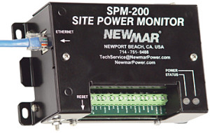
Remote Monitoring Of Critical Site Conditions: Read the rest of this entry »

Phase Three Series – Battery Chargers

February 4th, 2015 by Raymond Gibb

3 stage battery charger

Three Stage Battery Chargers, bulk, absorption and float

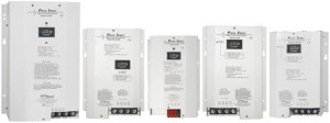
Phase Three series battery chargers interact with batteries to put them through the optimum three stage charging process, which provides for fastest recovery and ideal conditioning, maximizing battery performance and extending battery life. Read the rest of this entry »

DST-FB DC Power Distribution Panel

December 10th, 2014 by Raymond Gibb

DST-FB2


Newmar Telecom, manufacturing partner to GFS Power, Introduces a DC Power Distribution Panel Combining GMT Fuses and Circuit Breakers

The DST-FB panel, by Newmar, offers a unique combination of circuit protection utilizing both circuit breakers and GMT fuses in a single, 2 RU rack mount assembly.

Read the rest of this entry »

Sentinel – DC Power System

October 21st, 2014 by admin


Sentinel Rectifier System


Newmar Telecom, manufcturing partner to GFS Power, introduces the Sentinel, a 1RU DC Power System, with Built-in Load Distribution and SNMP Monitor.

The 1RU (1.75”) rack mount shelf accommodates three 600 watt hot swap power rectifiers at -48 VDC producing 33 amps, 1800 watts, total system output capacity.

Read the rest of this entry »

© GFS Power. Website by Mick's Design.